
The FastCCD installed in the endstation at CSX-1 is of the LBNL Fast CCD design. The sensor contains 1920 x 960 pixels of 30 µm x 30 µm and is arranged into two halves of 960 rows by 960 columns with the columns parallel to the long CCD axis. There is one output for each 10 columns (a “super column”) which results in 192 individual outputs and analogue to digital converters (ADC). The CCD camera can either be used in a traditional CCD with an x-ray shutter exposing the full chip, or in a framestore (frame transfer) mode by covering two quarters of the CCD with a light (x-ray) block effectively exposing half the chip along the column direction.
The analogue CCD signal is digitized by a custom designed fCRIC. Each fCRIC has 16 analogue inputs and digitizes with 13 bit precision and had 16 bit dynamic range. This is accomplished by having 3 gain ranges of 8x, 4x and 1x with an auto gain feature. In order to allow negative charge injection. The ADC is biased at a value of approximately 4096 (0x1000 in hex) with the exact value dependent on the ADC channel. The gain settings are stored in the two most significant bits of each ADC reading. The schematic of a single fCRIC chanel is shown in the LBNL fCRIC Circuit Diagram.
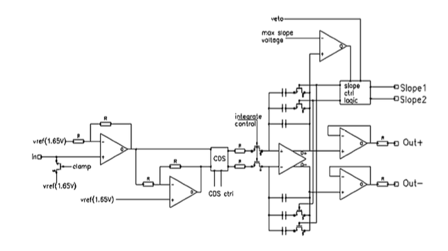
LBNL fCRIC Circuit Diagram
The specifications of the CCD are summarized below:
In treating the raw CCD data from the FastCCD there are a few important considerations related to the multi-gain behaviour of the fCRIC amplifier and digitizer. The raw 16 bit values that are recorded in the data file follow the 16 Bit fCRIC Data Format shown below with the two gain bits following the fCRIC Gain Setting.
| 15 | 14 | 13 | 12 | 11 | 10 | 09 | 08 | 07 | 06 | 05 | 04 | 03 | 02 | 01 | 00 |
|---|---|---|---|---|---|---|---|---|---|---|---|---|---|---|---|
| G1 | G0 | ERR | D12 | D11 | D10 | D09 | D08 | D07 | D06 | D05 | D04 | D03 | D02 | D01 | D00 |
| G1 | G0 | Gain | Pre-factor |
|---|---|---|---|
| 0 | 0 | x8 | x1 |
| 1 | 0 | x2 | x4 |
| 1 | 1 | x1 | x8 |
Here the two most significant bits record the gain setting for the encoded value. The least significant 13 bits hold the measured analogue value. The actual value is therefore related to the measured value by:
where \(A_{\mathrm{corr}}\) is the corrected intensity, \(A_{\mathrm{meas}}\) is the measured value by the ADC, \(G\) is the gain of the ADC and \(O\) is the bias offset.
Due to the multi gain nature of the fCRIC it is therefore necessary to take 3 dark images at different gain settings to obtain the different ADC offsets under these modes. As the lower gain settings are not subject to considerable contribution due to dark current it is usually justifiable to measure only the highest gain dark image repeatedly. Given 3 dark images for the different gain settings the images the following python pseudo code can be used to correct for dark current and gain:
import numpy as np

def subtract_background(image, dark_image, gain = [1, 4, 8]):
    gain_mask_8 = (image & 0xC000) == 0xC000
    gain_mask_4 = (image & 0xC000) == 0x8000
    gain_mask_1 = (image & 0xC000) == 0x0000

    cor_image = image.astype(np.float16)
    cor_image -= gain_mask_8 * dark_image[2]
    cor_image -= gain_mask_4 * dark_image[1]
    cor_image -= gain_mask_1 * dark_image[0]

    gain_image = (gain_mask_8 * gain[2]) + (gain_mask_4 * gain[1]) + (gain_mask_1 * gain[0])

    return (cor_image * gain_image), gain_image